Quest For Motors' Hidden Abilities and New Potentials
Lecture 15: The Case of the Three-phase Induction Motor
The rotating magnetic field-type motor uses three-phase AC to secure the electricity-to-mechanical energy conversion based on an electromagnetic-induction mechanism that uses a squirrel-cage rotor. A major difference between the shaded-pole motor – which I explained in the previous edition of this column – and the six-coil concentrated wind – which I cited in a related explanation – lies in a complex winding called “distributed winding.” The number of the north and south poles that appear around the void is referred to as a “pole number.” The minimum pole number is 2, and it can increase as an even number (4, 6, 8…) based on the wire-winding method. In a magnetic field’s rotating speed, if the frequency is ![]() , it will be
, it will be ![]() times per second for a bipolar winding wire,
times per second for a bipolar winding wire, ![]() /2 times per second for a quadrupolar winding wire, and
/2 times per second for a quadrupolar winding wire, and ![]() /3 times per second for a sexpolar winding wire.
/3 times per second for a sexpolar winding wire.
Illustration 15-1 features a photo of a three-phase squirrel-cage-type induction motor that was designed for a desktop experiment. The stator’s winding wire is arranged and connected to form a quadrupolar magnetic field.
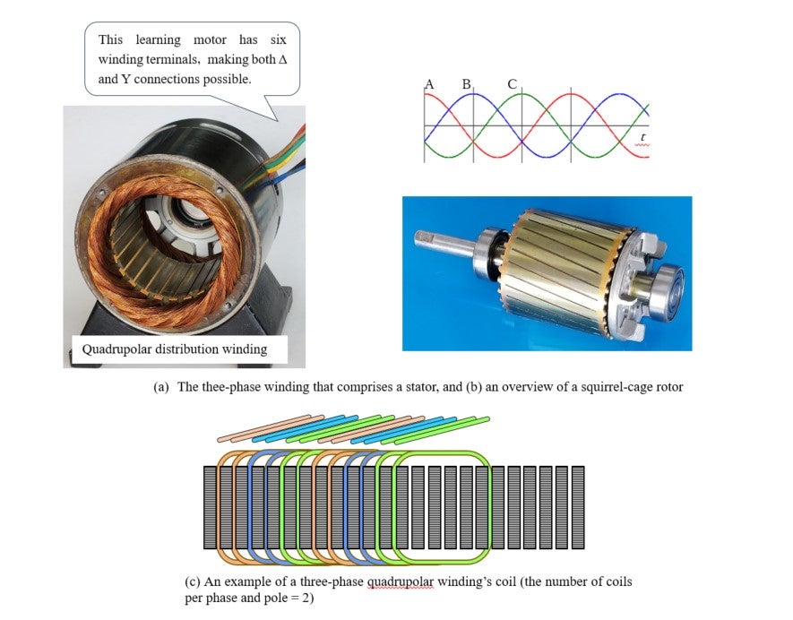
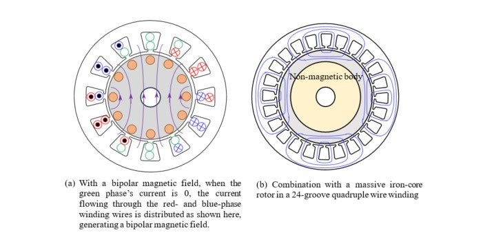
Illustration 15-2 shows a description of a rotating magnetic field. (a) is a case where a bipolar magnetic field rotates. (b) represents a quadrupolar rotating magnetic field with 24 coils. Here, many coils are used for the electromagnetic induction to work as effectively as possible to form a smooth rotating magnetic field both temporally and spatially.
The equivalent circuit, and analysis and calculation by using it
The squirrel-cage type induction motor has been subject to various researches by highly intelligent people. Such researches include those on relations between individual components’ structures and materials, and torque and current. One of the major achievements from the time before the calculator was invented was an analytical/calculation method known as the “equivalent circuit,” which was devised based on the transformer’s equivalent circuit. This is a calculation tool with a mechanism where magnetic flux flows through the iron core inside a motor, causing electromagnetic induction with the current flowing through the coil, and generating power as well. In this column, the term “equivalent” is used to mean that one can forget about magnetic field and magnetic flux, and perform calculation on an electric circuit as a mechanism comprising voltage and current only. “Equivalent circuit” is English, but it is called “Einsatzkreis” in German. “Einsatz” apparently has some nuance as something replaceable.
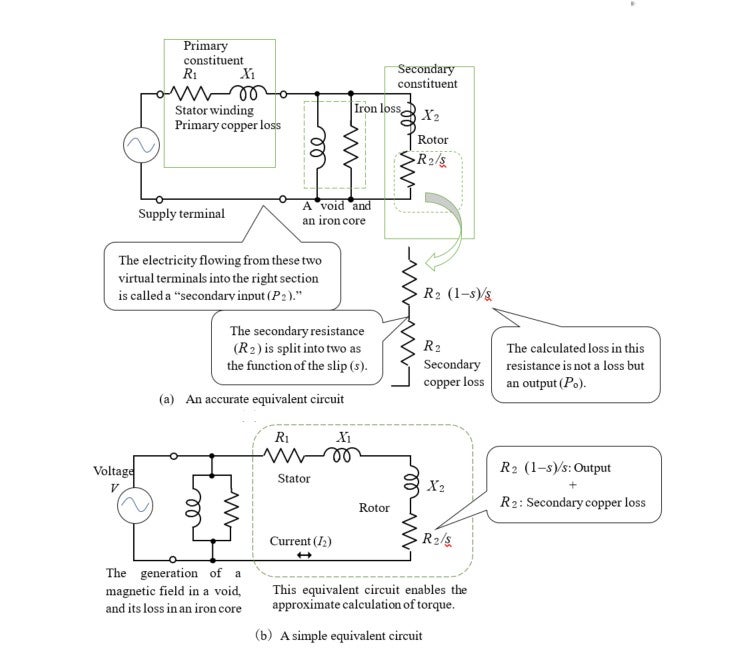
Illustration 15-3 shows two prevalent circuit representations. In (a), the left portion represents a stator winding, while the right portion is a rotor. The one in the center (a parallel circuit of resistance and inductance) expresses the nature of the void and the iron cores (of both sides). On the right, the rotor’s resistance value has a variable number, ![]() , which represents rotating speed, and is defined as follows:
, which represents rotating speed, and is defined as follows:

This is called “slip,” which is a gap with the magnetic field’s rotating speed (synchronous speed). The motor’s rotating speed of 0 is ![]() = 1, and its synchronous speed is
= 1, and its synchronous speed is ![]() = 0. As described here, the equivalent circuit in (a) contains physical implications well.
= 0. As described here, the equivalent circuit in (a) contains physical implications well.
The circuit in (b) slightly sacrifices such physical implications. By using this, one can easily calculate the electric power to be consumed by the winding wire and the rotor, and the output and the torque of the rotor.
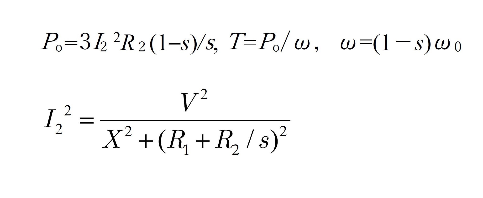
The following calculation results are important:
1) The rotating rotor’s resistance component can be expressed as “![]() ”
”
2) If the current is “![]() ”, “
”, “ ![]() ” is the power (= output
” is the power (= output ![]() ) that can be obtained from the shaft.
) that can be obtained from the shaft.
3) The loss inside the rotor is: ![]()
4) The relation between the torque, “![]() ” , and the output, “
” , and the output, “![]() ” is:
” is: ![]()
5) And:
Therefore:
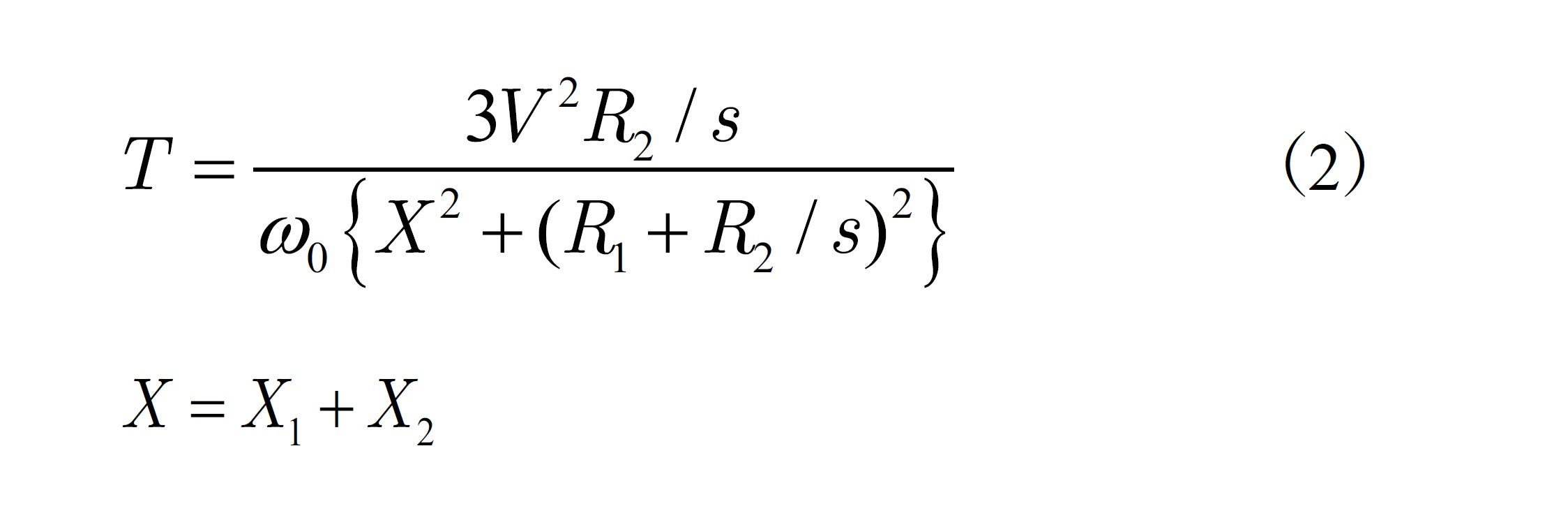
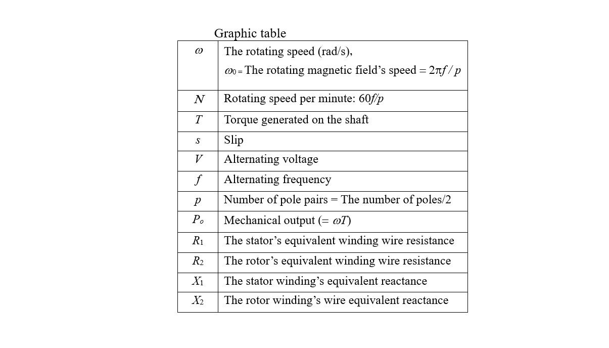
As shown above, the torque (![]() ) become
) become ![]() ’s function, closely linked to electric resistance (
’s function, closely linked to electric resistance (![]() ), which is determined based on the conductor and the dimensions to use. These relations are described in the chart in Illustration 15-4.
), which is determined based on the conductor and the dimensions to use. These relations are described in the chart in Illustration 15-4.
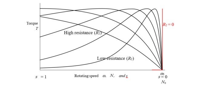
◇ For a model whose starting torque should be large, either make the conductor narrow, or use an alloy such as brass. With this design, the output (![]() ) does not become large, as the torque decreases with the speed.
) does not become large, as the torque decreases with the speed.
◇ The starting torque will be low if copper is used for the conductor and the short-circuit ring, or thick, die-cast aluminum is used. However, the torque will become large due to the high speed, resulting in a large output and a high efficiency (mechanical output/electric input).
◇ For industrial general-purpose motors, their conductors’ cross-sections are processed to adjust the motors’ overall torque characteristics.
As indicated in Formula (2) above, as the secondary conductor’s resistance, ![]() , approaches zero infinitely, the results will be as shown in the red line. As “superconductive” means zero resistance, it seems that, theoretically, torque is not generated in an induction machine. Could this be really the case? This will be an area of major contention in the next edition of this column.
, approaches zero infinitely, the results will be as shown in the red line. As “superconductive” means zero resistance, it seems that, theoretically, torque is not generated in an induction machine. Could this be really the case? This will be an area of major contention in the next edition of this column.
What happens when  = 0?
= 0?
The question “What happens when ![]() = 0” remains unsolved, too. For electromagnetic induction to occur, slip was necessary between the speed at which the magnetic field rotates and that of the rotor. What happens when the rotor’s speed reaches that of the magnetic field? Here lies the problem. As electromotive force is not generated on the rotor, current does not flow in normal conduction. However, current can continue to flow in a superconductive state. Such a state is no longer that of an induction machine, but of an asynchronous machine. To talk about the superconductive motor as a technical topic, I would recommend that you casually check, among others, the relations between the types of synchronous motors and induction machines. Let’s make it the theme for the 16th edition of this column. In addition, to explore deep mysteries of motors, let’s return to magnetic induction, which is not the same as electromagnetic induction, and also to the issue of non-Lorentz force, the topic in the 11th edition of this column. Thus, we should talk how a complex magnetic phenomenon mysteriously transforms itself into a simple equivalent electric circuit.
= 0” remains unsolved, too. For electromagnetic induction to occur, slip was necessary between the speed at which the magnetic field rotates and that of the rotor. What happens when the rotor’s speed reaches that of the magnetic field? Here lies the problem. As electromotive force is not generated on the rotor, current does not flow in normal conduction. However, current can continue to flow in a superconductive state. Such a state is no longer that of an induction machine, but of an asynchronous machine. To talk about the superconductive motor as a technical topic, I would recommend that you casually check, among others, the relations between the types of synchronous motors and induction machines. Let’s make it the theme for the 16th edition of this column. In addition, to explore deep mysteries of motors, let’s return to magnetic induction, which is not the same as electromagnetic induction, and also to the issue of non-Lorentz force, the topic in the 11th edition of this column. Thus, we should talk how a complex magnetic phenomenon mysteriously transforms itself into a simple equivalent electric circuit.
