Quest For Motors' Hidden Abilities and New Potentials
Lecture 14: Mysteries of the Induction Motor – Considerations based on a Transformer Model
In the previous lecture (Lecture 13), I provided commentary on the inductor motor. This lecture focuses on the induction motor. There are several types of induction motor and the main one is used world widely as industrial motors. In this lecture I pick up a curious type of induction motor. The turntable of a record player, which is now an antique, was driven by a shaded-pole motor, and vacuum tubes reproduced melody of classical music. In this lecture I pick up this curious induction motor involving a structure as an inductor motor.
From transformer to motor
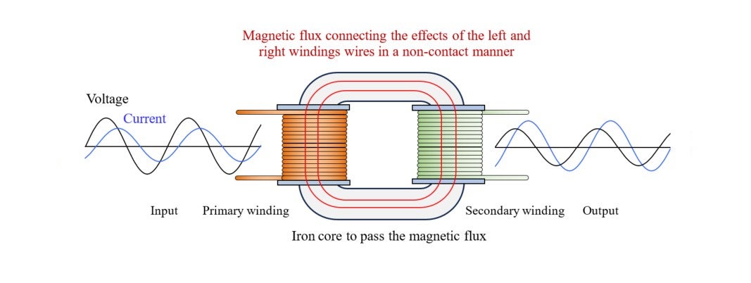
First of all, what is induction? The term “induction” herein means electromagnetic induction. Let’s review what it is by beginning with a transformer, which is a device to convert an alternating voltage/current to another alternating voltage/current. Its basic structure is such as shown in Image 14-1 below; composed of two windings and an o-type iron core.
The input-side winding is called the primary winding and the output-side one is the secondary winding. For example, when converting the voltage of 100V to another voltage of 20V, you need to make the ratio of the winding turns between the primary and secondary winding 5:1. Suppose an electric bulb is connected to the secondary winding, and a current of 1A is flowing through it. This means that a current of 0.2A is flowing through the primary winding. The input electric power is 100 x 0.2 = 20W, and the output from the secondary winding is 20 x 1 = 20W. Hence, (ideally) the input power is equal to the output power.
Shading coils for a shaded-pole motor
A transformer is a device to convert electric power into electric power. With a little twist, can we make a mechanism (motor) to convert electric power into motion (=mechanical power) ? Mechanical power is defined as rotary speed x torque. That is, the mechanism is to govern:
(Voltage x current) (Speed x torque)
This is a basic theme in electrodynamics.
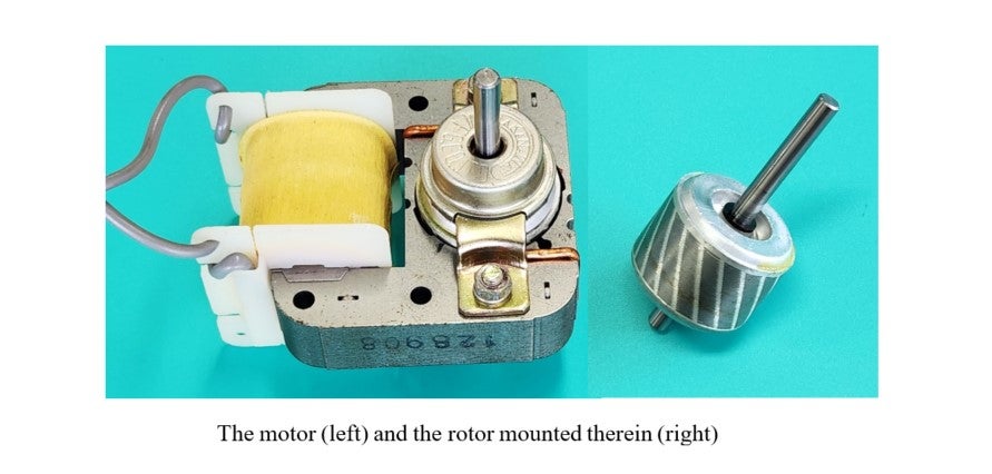
A typical device equipped with such a mechanism is the shaded-pole motor, shown in Image 14-2 below. The photo in Image 14-3 features the structure of a rotor (rotating part), with a short-circuiting mechanism in three places. One of them is the rotor’s squirrel-cage conductor, and the other two are the couple of coils installed at the corners of poles where the stator iron core becomes narrow.
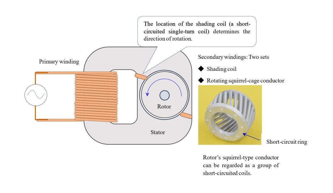
English verb “to shade” is means to “block.” What is to be blocked? It is magnetic flux, but it’s not easy to answer the question clearly with simple words. The later figure in Image 4-7 may be somehow helpful.
Let’s make a detour, and first ask ourselves what would happen if there were no shading coils. In response to this question, Mr. W, who has spent the past decade or so researching permanent-magnet motors, said, “You cannot make a motor without a shading coil.”
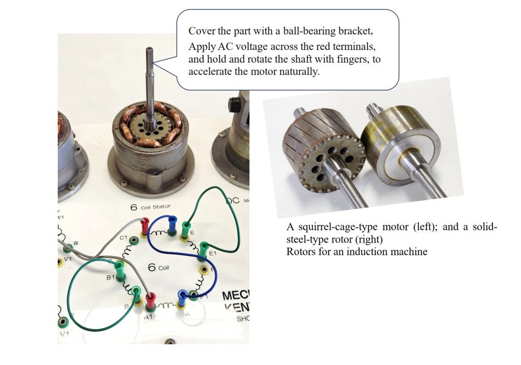
Experiments that start with this Q&A session may give a scare to those researchers who are confident about their motor designs and control. Later, after making some arrangement, I demonstrated a variety of experiments for three young researchers, including Mr. W. Here’s a partial explanation on how it went. We used MechatroLab. This desktop testing device with three types of stators and a variety of rotors can demonstrate a wide range of fundamental motor phenomena.
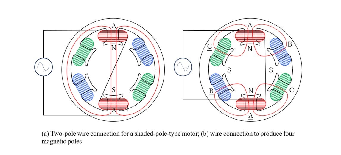
Our experiment uses two types of rotors shown in Image 14-4 below, i.e., a squirrel-cage type (left) and a solid-steel type (right). The photo shows a squirrel-cage rotor installed in a six-coil stator. Image 14-5below explains the reasons for the six coils. These coils are referred to as “A,” “A,” “B,” “B,” “C,” and “C” respectively. First, connect A with A in series, and apply a 50Hz AC voltage to them. There are two methods available to connect A with A:
Method 1)To produce two magnetic poles (“NS” or “SN”) when a direct current passes though the two coils, and
Method 2) to excite magnetic poles in the same polarity (“NN” or “SS”) when a direct current is supplied.
Image 14-5 (a) and (b) explain the difference. Method 1) generates a vertical two-pole magnetic field which is similar to the shaded-pole motor we are discussing. Image (b) shows the case of Method 2), which creates a four-polar magnetic field by magnetizing the facing poles in the same polarity. The teeth of current-free combinations, BB and CC, provide magnetic paths, as shown in the wire connection in the photo in Image 14-4 below.
Symmetry and where it breaks
The title may remind you of cutting-edge physics. Albert Einstein derived the Lorentz transformation from a request for an electromagnetic symmetry in a unipolar generator, and advocated the special theory of relativity – electrodynamics of moving bodies – in 1905. Lecture 12 was themed on the special theory of relativity. The 2008 Nobel Prize in Physics went to Yoichiro Nambu, Makoto Kobayashi, and Toshihide Maskawa for their researches on the symmetry violation (breakig) on the reasons for the existence of the universe.
Let’s bring symmetry and asymmetry into the science of motors.
First, I connected stator’s wire connection in opposite two poles, and covered it with a bracket to ensure that the rotor would rotate smoothly. However, even after increasing the voltage gradually, the rotor remained still – it did not start moving – as Mr. W’s prediction. He may have had an image like the one in Image 14.6 in his mind. This appears bilaterally and vertically symmetric in mechanical construction, and the magnetic field is bilateral symmetrical. It is due to this symmetry that there seems no reason for the rotor to rotate in either direction. Mr. W’s answer seems right in this regard. However, we may note D’Alembert’s principle of virtual displacement. What if the rotor – staying still – is actually moving (or displaced) CW or CCW? This is to check for a symmetry breaking. Another item to note is initial conditions. In this experiment the rotor is standstill when applying a voltage to the winding. This is merely an example (option) of initial conditions.
This is where my performance starts. In the configuration in Image 14-5(a), while raising the voltage, I held the shaft with thumb and forefinger, rotated it CW (clockwise), and released it. Then the rotor accelerated its speed in the same direction, demonstrating its performance as a motor. When I stopped the movement with my fingers, and rotated the rotor CCW, the rotor accelerated its speed in the direction. This experiment turned out to be a demonstration of the principle of single-phase squirrel-cage motor – the first-time experience of its kind for the three researchers! Revolving the rotor in such a way was a modification of initial condition.
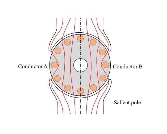
Image 14-6 What will happens if a bilateral symmetrical alternating field is applied to a bilateral and vertical symmetric construction. Suppose that the overall magnetic flux is  . Conductors A and B are short circuited, through which passes. As a result, back-emf
 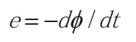 will be generated and a new current flows in these closed conductors. As this is alternating and the time-average is 0, you may consider that no motion will take place. However, if the rotor is revolving either CW or CCW even slightly, part of the initial conditions -symmetry- will be broken. When you try to work out what will happen, you may ignore bearing-generated braking force for simplicity.
From instability to stability
Electrodynamics can be developed on paper using mathematics. By setting up a slight speed in a CW or CCW direction as an initial condition, you may seek a formula for the electromotive force generated after the conductors cut the magnetic field and the current created by the force, to find that the force to accelerate a motion as an interaction with the basic magnetic field acts on the conductor. In a theoretical thinking, an issue remains as to whether to be convinced of the calculation on paper. The aforementioned finger-using experiment does not leave room for this question. This experiment revealed that Image 14-6 is an unstable symmetry; the rotor starts to move in the direction of an external force, accelerate, and eventually reach a stable speed. This is a characteristic of a single-phase squirrel-cage induction motor.
Next, we replaced the squirrel-cage rotor with the solid-steel rotor shown in Image 14-4 (right). The rotor did not accelerate even with the assistance of fingers, and stopped rotating. This is a stable symmetry. It is not easy to accurately understand and explain the difference between the instability and the stability that are seen in these two types of rotors.
Once again we replaced the rotor with the squirrel-cage-type, and changed the stator’s wire connection to produce a four-pole magnetic field. Similar phenomenon was seen. As part of its major features, the squirrel-cage rotor can work regardless of number of magnetic poles.
What exactly is the short-circuit coil for?
Once again, please look at the winding connections in Image 14-4, which shows that the coils of B and B are short-circuited respectively with a banana jack lead wire. The rotor self-activated in a CCW direction. Next, we short-circuited CC instead of BB, to see the rotor start to rotate in a CW direction. This is the opposite direction of the case with shading coils shown in Image 14-3. In this case as well, the induction motor demonstrated one of its mysterious features.
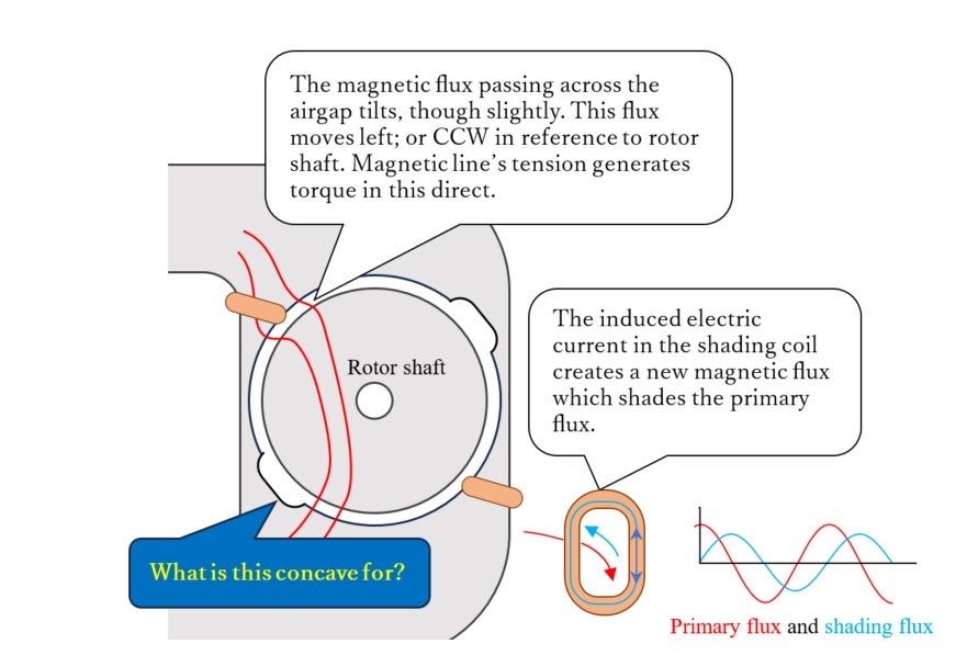
Image 14-7 shows important points on the system of the shade-pole motor. As depicted here the function of the shading coil is to induce additional magnetic flux which lags behind the primary flux by 90 degrees. Thus, the induced flux is not to block the primary flux but to modify it. The shading coils or shaded poles clearly break the symmetry.
The rotor self-activates even the absence of shading coils!
Because of this asymmetry, the squirrel-cage rotor may start. Plausible explanations are provided in textbooks and on websites, as well.
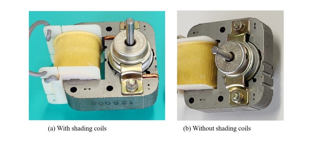
For the final check, we cut and removed the shading coils as shown in the photo in Image 14-8. A clear difference as compared with the structure seen in Image 14-6 is the existence of two concave portions (shallow grooves). We connected power supply terminals and raised the voltage. The results were:
- The rotor didn’t start with a low voltage at which activation occurs with shading coils. Assistance with fingers was ineffective.
- The rotor started after the voltage was raised close to the rated 100V, in the same direction as the case with two shading coils.
In considerations about generation of force or torque, we must be careful about the consistency of relevant elements such as prerequisites, introduction of Gauss’s theorem (on surface and volume integral), and boundary conditions. Though this lecture isn’t intended to speak of them, one matter requires attention is the principle of “action and reaction.” With this principle, the torque calculated in the stator and that calculated in the rotor must be equal but opposite. Here the airgap is the boundary between stator and rotor. According to a British engineer, doubts were raised on the principle of action and reaction in the history of electromagnetism as science, and the system known as the theory of Maxwell today seems to have been established after overcoming those doubts.
As there is a conductor inside the rotor, electromagnetic induction causes electric current to flow, and there is an electromagnetic field around the current, it may be possible to explain how torque is generated. However, with absence of electric current or coil on the stator’s iron core in the machine shown in Image 14-8(b), reaction torque doesn’t seem to be generated. Then how can one rationalize the use of the action-and-reaction principle? The answer can be found in the non-Lorentz force; the previously explained force or torque owing to the concave structure pointed out in Image 14-7. Two concaves on the stator core cause the generation of force, and one can likely use the geometric calculation on the B-H coordinate plane as a basis to work out. The derivation of Teare’s hysteresis-based torque formula (a non-Lorentz force), published in AIEE in 1940, is easy to understand. Teare discussed a complex, non-linear problem and clearly explained why the hysteresis major loop can be the cause of output power but minor loops decrease it in association with stator’s teeth. His geometric calculation principle can be applied to the effect of concaves on the stator core, which is a type of inductor. Lecture 11 (The mystery of non-Lorenz force) discussed this. It’s amazing as noted in the present lecture that this simple structure can produce torque combined with electromagnetic induction.
In the next lecture, let’s feature the three-phase squirrel-cage induction motor, which is widely used for industrial applications.