Quest For Motors' Hidden Abilities and New Potentials
Lecture 6: The Advance of Electronic Devices and Motor Technology
Among all mysteries surrounding motors, the biggest one is the abundance of their kinds. To drive these various types of motors, a device is needed to control the supply of current from an electric source in the proper manner. To meet this need, many kinds of electronic devices were developed and are being used in a variety of ways. Let us briefly review how these electronic devices came to be developed, and how they stimulated the emergence of new motors.
1. Early electronic technology to control the motor's movements
When speaking of types of motors, one may start by saying, “There are direct-current (DC) and alternating-current (AC) motors.” This classification is based on the observation that some motors rotate simply by applying direct current, while others rotate simply by applying alternating current. Batteries were developed at an early stage in the development of electric technologies. The DC generator was invented to replace batteries, and it was found to work as a DC motor as well. After Nikola Tesla saw a DC motor producing intense sparks as it rotated, he came up with the concept of the AC motor, as I wrote in the first episode.We shall begin our story then from the standpoint of DC and AC motors.
Controlling a DC motor supplied by an AC power source – Adjusting speed
In an AC system, power is transmitted over long distances under a high voltage using transformers. It was difficult with early technologies to sufficiently raise the voltage to achieve DC power transmission. Though power is also transmitted using direct current today, AC power transmission is still the norm. An AC motor, whose rotational speed is determined based on its power source’s frequency, is not suitable for wide-range speed adjustment under the normal mains frequency of 50/60Hz; DC motors are suitable for such speed adjustment.
Therefore, it was natural in the history of industrial technology for the need to emerge to rotate a DC motor with an AC power source. The controlled rectifier device was invented to satisfy this need.
Dipole discharge tube to change alternating current to direct current
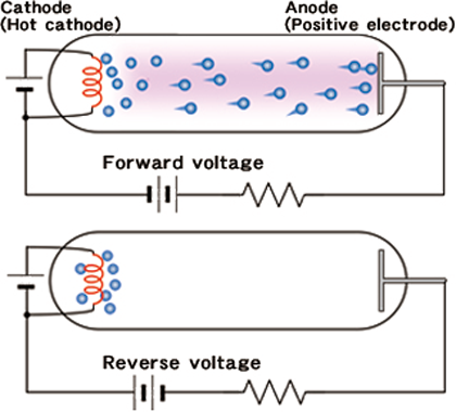
(rectifier tube)
The technology to convert alternating current into direct current is used when the latter is more suitable for applying voltage for a motor’s winding. Though a semiconductor device is used for that purpose now, there was a time when a discharge tube would be used instead. The discharge tube constitutes one of the major breakthroughs that occurred in the history of electronic engineering for motor control.
In a typical discharge tube, as shown in Illustration 1, rare gas (helium, neon, argon, etc.) is enclosed in a glass ball. A discharge tube has two electrodes: an anode, which is made of metal (or carbon) and to which positive voltage is applied, and a hot cathode, which consists of a filament heated up to make electrons escape. When a voltage is applied between the anode and cathode, the electrons released by the cathode start moving toward the anode at an increasingly high speed, and collide with gaseous atoms to ionize them, thus creating more free electrons. This causes the gas to glow, and this state is called a plasma.
What will happen if the positive and negative sides of the voltage applied to the two electrodes are interchanged? The current cannot be reversed in this way because the anode, which is unheated, is unable to discharge electrons. This fact indicates that the device has the effect of transforming alternating current into direct current (rectification). If the tube is in a vacuum state, containing no gases, only those electrons discharged from the heated cathode form an electric current, and therefore a large current cannot be rectified. Whether vacuum tube or discharge tube, if it was equipped with two electrodes it was called a diode. Today, the term "diode" is usually used to refer to a semiconductor device.
It was after the emergence of small semiconductor diodes that they came to be widely recognized as essential elements to drive motors.
From diode to triode: The birth of the controlled rectifier
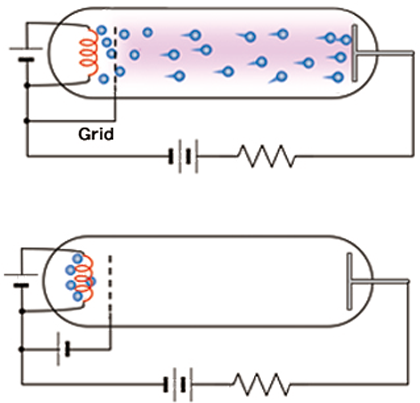
in triode discharge tube
Another advantage of the use of plasma was that, by adding another electrode, it became possible to control the timing to start electrical conduction, as illustrated in Illustration 2. The additional electrode, which was introduced to affect the electric field around the cathode, was formerly called a grid but now is called a gate. Even when a positive voltage is applied to the anode, plasma will not be generated if the electrons released from the cathode are prevented from accelerating. When a positive voltage is applied to the gate, the electrons are accelerated as they pass through the gate and generate plasma. This enables a large current to flow. Once current is flowing, the gate cannot be used to block it. To stop the current, the anode voltage must be reversed, as is the case with a diode. Because the start of electrical conduction can be controlled with the voltage applied to the gate, this device is called a controlled rectifier. The discharge tube called the thyratron (Illustration 3) is an example.
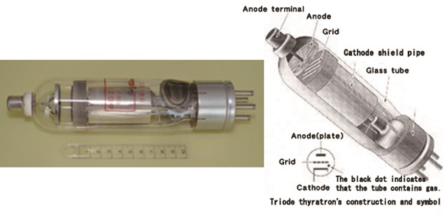
Speed control of a DC motor and regenerative drive
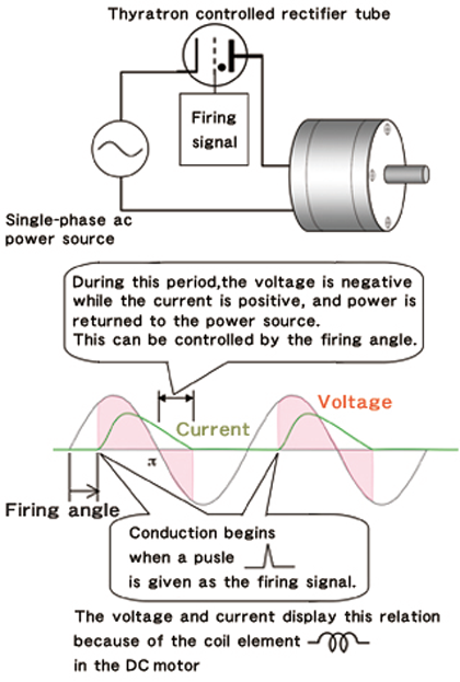
the speed of a DC motor.
Illustration 4 shows a simple example of using this gas tube for speed control of a DC motor. Here the DC motor is driven from a single-phase AC supply, but the average voltage applied to the motor can be adjusted by controlling the firing angle to start conduction of current. Since the speed of a DC motor is roughly proportional to the voltage, the speed can by reduced by increasing the firing angle up to 180 degrees (π).
It is seen that the current continues to flow even after the voltage is reversed. During this period the electric power, which is the product of the current and voltage, is negative. This means that the kinetic energy of the rotor and load is converted to electric energy and fed back to the power supply. In this example, energy feedback takes place during a very short period within the half cycle.
Subsequently, it became possible to continually feedback the mechanical energy to the power supply by using several thyratrons. This was an effective braking method of the motor, referred to as regenerative braking, and found to be an efficient way of using electric power.
Cycloconverter
Nowadays we use a device called an inverter to drive an AC motor in variable speed mode. This will be discussed in the 8th installment of this series. There is a similar but different device to convert the frequency from the normal 50/60Hz to a lower frequency. Called a cycloconverter, it employs thyristors, which is a type of semiconductor device that will be covered in the 7th installment. Before the thyristor was invented, the thyratron and its family gas tubes were used instead in the cycloconverter. This technology may have been the origin of power electronics.
2. From discharge tube to solid-state device
The age of solid-state devices started in the 1960s, when they replaced discharge tubes. The technology to control the flow of current developed by replacing plasma with impurity semiconductors as the current path. The transistor is a representative example of such devices. Simultaneously, various other electronic devices were developed, which stimulated advances in motor technologies and led to the birth of new motors. In order to examine this history, we must first learn some basics of semiconductor devices.
2-1 PN junction
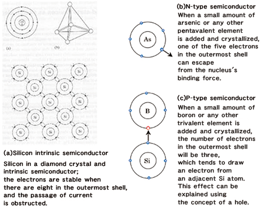
As shown in Illustration 5(a) the crystal of silicon has a diamond structure, which allows the passage of very little current. When a small amount of a pentavalent element is added while forming this crystal, one of the outermost electrons is released from the bind of the nucleus and starts moving freely, as shown in Illustration 5(b). This is similar to the state of free electrons in a plasma.
If a trivalent element is added instead, it will tend to take away an electron from the outermost shell of an adjacent silicon atom, as shown in Illustration 5(c) . The location where an electron has been removed is called a hole, since it acts like the hole of a missing electron, and can be treated as a positively charged electron. Unlike a positron, however, the hole behaves as if its mass were three times that of an electron.
Such a crystal is called a semiconductor because it is not as conductive as a metal, but more conductive than an insulator. While pure silicon crystals are called an intrinsic semiconductor, those crystals to which tri- or pentavalent elements have been added are called impurity semiconductors, for which there are two types:
Holes used as charge carriers: P-type (added with trivalent elements such as boron and indium), or
Free electrons used as charge carriers: N-type (added with pentavalent elements such as phosphorus and arsenic).
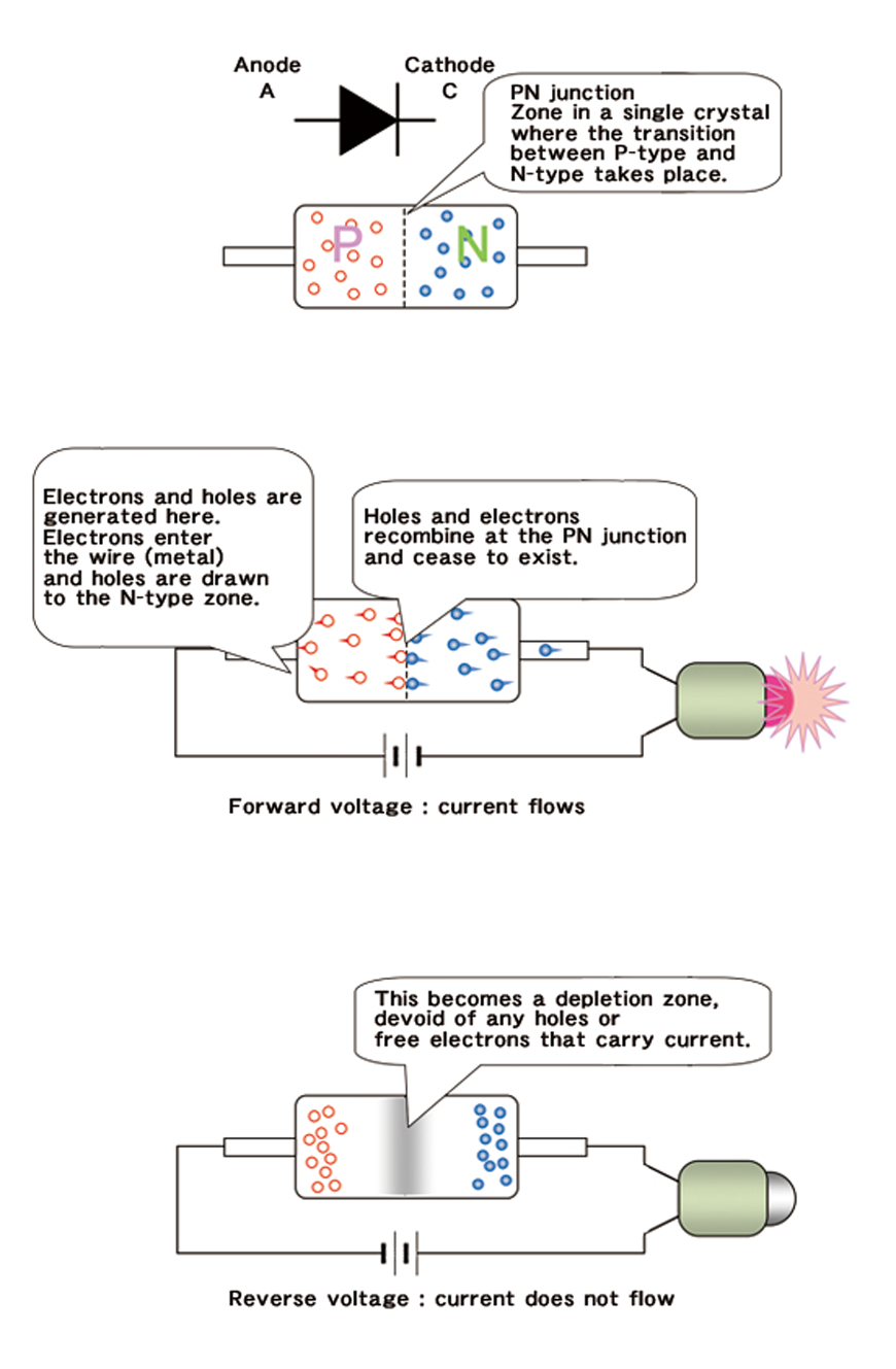
The transitional zone between P-type and N-type semiconductors formed within a crystal structure is called a PN junction (Illustration 6(a)). Illustrations 6(b) and (c) illustrate the rectification effect of a PN junction. A PN junction has three major advantages over electron phenomena in a vacuum or a plasma:
(1) Current in a semiconductor is generated by holes as well as free electrons. When a free electron encounters a hole, they combine. This phenomenon is called recombination, and means that both the free electron and the hole cease to exist.
(2) A PN junction does not require a filament like a vacuum or discharge tube. Furthermore, it is compact and mechanically robust.
(3) A PN junction’s forward anode-cathode voltage is low.
Despite these merits, the PN junction is not without problems. For example, when the voltage is switched from forward to reverse, any free electron or hole remaining will momentarily create a large reverse current. The time it takes for this large current to disappear completely is called the reverse recovery time, and the considerable efforts to shorten this time advanced power electronics to its level today.
2-2 Elements that react to light and magnetic forces
The science of semiconductors bore many fruits, and led to major changes and progress in motor control technologies. While the transistor was typical of devices in which a small current or voltage is used as the input signal to control large currents, devices called the photodiode, phototransistor, and photo coupler, which respond to light, were invented.
The Hall effect had long been known as a magnetic induction effect, but the use of semiconductors allowed the development of sensitive Hall-effect elements (The Hall effect was named after Edwin Herbert Hall, a physicist who discovered this effect).
In the next article, we shall examine how the development of transistors employing Hall-effect elements and PN junctions led to advances in small motors.
Coined the word "plasma"
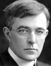
Born and raised in Brooklyn, New York, Langmuir studied at Columbia University and then Göttingen University in Germany, before returning to the United States to teach at an engineering college in New Jersey. Perhaps because he became disillusioned with teaching or was disappointed about the low salary there, Langmuir joined the then newly opened General Electric Company (GE) Research Laboratory in Schenectady, New York, determined to work in industry, in 1909.
It was the laboratory’s director who suggested to Langmuir, who was prepared to do routine work as a company employee to work to directly benefit the company, that he should look around at what was being done at the laboratory and decide what to do himself. Recalling these days later in his life, Langmuir referred to this research laboratory, where he worked for the following 40 years, as having "more academic freedom than I had ever encountered in any university.”
One of Langmuir's first achievements was to enclose nitrogen in an incandescent light bulb to improve its life. He filled a bulb with a chemically inert gas, an idea which was the opposite of the conventional thinking of improving the degree of vacuum.
In 1928, during his research on electric discharges in gases, Langmuir coined the term "plasma." By this term, he referred to a state where part of the molecules comprising a gas is ionized to form free electrons and ions, which appear glowing either dimly or brightly to the naked eye. The ionized state of a gas had long been studied in Europe, but Langmuir’s work stands out in that he invented an electrode probe to measure the state of plasma, and defined the electron temperature, a physical quantity to indicate the state of plasma.
A vacuum tube is a device which consists of a glass tube the inside of which is made vacuum, and the quantity of electrons flowing between electrodes is controlled to amplify or otherwise control a signal. Meanwhile, a glass tube can be filled with a rare gas like argon or neon and a thermionic cathode used to create plasma; this device can be used to rectify large currents. Langmuir conducted research in this area as well beginning around 1914. A thyratron is a gas tube in which additional electrodes are introduced so that rectification can be controlled from the outside. GE made this into a product in 1928. Subsequently, thyratrons began to be used to control DC and AC motors. It was from around this time that Langmuir began to undertake investigations in diverse areas. In 1920, Hermann Walther Nernst, who taught Langmuir at Göttingen University, was awarded the Nobel Prize in chemistry, and Langmuir himself was awarded the same prize in 1932 for his contribution to surface chemistry. Incidentally, the thyristor, a semiconductor device that simulated the thyratron’s function, was developed by GE engineers in 1957, the year Langmuir passed away.
