Quest For Motors' Hidden Abilities and New Potentials
Lecture 4: Motors and the Flow of Energy in Electromagnetic Fields
The theory that Albert Einstein presented under the title, “Zur Elektrodynamik bewegter Körper (On the Electrodynamics of Moving Bodies),” in 1905 is what is today known as the special theory of relativity. When light is observed from two different observing systems that are in uniform motion, the light’s propagation speed is the same (c = 300,000km/s), but a different frequency is observed by each of the two systems. Einstein’s theory is that the length of an object differs depending on from where the object is observed, and that there is no “absolute standard of rest,” and all coordinate systems are relative.
Energy Flow in an Electromagnetic Field and Principles of Motors and Power Generators
The electromagnetic wave in the outer space is a form of light, and carries energy. John Poynting of Great Britain propagated a theory on the flow of such energy. In his theory, the density of an energy flow (P) is the vector product of the electric field intensity (E) and the magnetic filed intensity (H).
P =E ×H
This expression is even simpler than Einstein’s ![]() formula.
formula.
Since James Maxwell’s electromagnetic formula follows Einstein’s theory, Poynting’s vector, led from the formula, is believed not to contradict the theory of relativity. Nonetheless, Poynting probably did not give so much consideration on the theory of relativity.
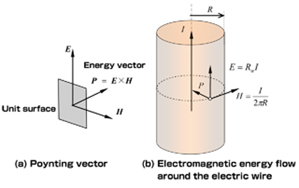
Figure 1 explains Poynting’s widely known energy flow, which is shown in student textbooks. The figure describes two facts about how copper loss occurs due to a current that runs a copper wire with a circular cross-section.
The magnetic field intensity around an electric wire with a radius of R (H) is as calculated based on Ampere's rule (See Figure 1). If the electric resistance of the copper wire per unit length is ![]() , the electric field intensity (E), which is the product after being multiplied by the current (I), will be
, the electric field intensity (E), which is the product after being multiplied by the current (I), will be
As shown in the illustration, the directions of the electric field vector (E) and the magnetic field vector (H) are perpendicular to each other, and the Poynting vector makes its way to the inside of the electric wire. In this case, the size of the vector’s outer product (E x H) will simply be the result of multiplying the E with the H of each point.
![]() When multiplied with the area per unit length
When multiplied with the area per unit length![]() , the area per unit length will be
, the area per unit length will be , which equals EI, and matches the well-known result.
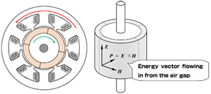
However, when, instead of simply running a current in the electric wire, the conditions of the magnetic or electric filed is modified, part of the conductor (object) will try to rotate. It is this phenomenon that is used to make motors rotate.A further deep analysis and calculation would reveal that a motor can be made with not only a conductor but a magnetic body as well. Here, this illustration explains that there is a gap between a stator and a rotor.
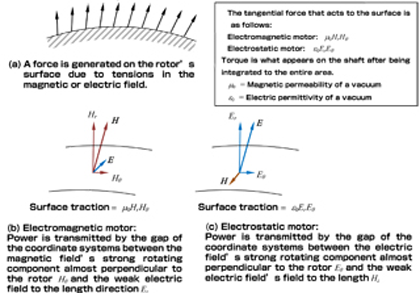
A motor rotates likely because a tangential force acts to the rotor’s surface.Maxwell’s notion on stress tensor explains such a tangential force as the tension of magnetic and electric lines of force, as shown in Figure 3(a), and this notion can be linked to Poynting’s vector.
Figure 3(b) shows a motor that uses a magnetic line of force, while Figure 3(c) shows ones that uses an electric line of force. Though some facts show that Poynting was considering linking his theory to the motor, but he did not do so successfully. Poynting’s energy flow speed is, regardless of coordinate systems, the same as the speed of light (c), but its size varies depending on the coordinate system. This is a mechanical work where the gap between two coordinate systems flows in a vacuum.
The above theory is what I propagated, and can be described in the formula below:
(Poynting vector in the stator’s coordinate system) – (Poynting vector in the rotor’s coordinate system)= Power vector
There is a space between the stator and the rotor. This gap is called an “air gap,” through which an electromagnetic energy passes. The air gap, though filled with the air and other gasses, possesses the properties of vacuum. In this article, under a more detailed analysis, a vacuum is considered to transmit power that is the source of a mechanical work. In the theory of relativity, the speed of light (c) is constant due to the coordinate system; however, due to differences in energy flows per unit time, the gap in values observed between coordinate systems can be considered to be power. A rotary machine becomes a motor if this power is positive, and it becomes a power generator if this power is negative. Contemporary hydraulic and wind generators work based on this theory in a way.
Consideration on Cases where the Rotor-stator Air Gap is Narrow
The air gap between the iron cores of a rotor and a stator can be short, so long as the two components do not mechanically contact each other. This is because the shorter an air gap is, the stronger its magnetic field becomes and the more density to transmit power is generated. Photo 4(a) shows an extremely special squirrel-cage type induction motor, whose air gap is approximately 1/10 of those of normal motors’. This motor is special because:
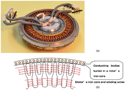
When a squirrel-cage type induction motor’s air gap is made excessively narrow, loss (stray load loss) will be incurred due to the slot-caused pulsation of the air-gap flux; this motor, however, has a narrow air gap because stray load loss can be reduced with the stator rotor based on extremely minute and complex operations.
Unlike such internal-combustion engines, though, electric motors cannot be made rotate smoothly by further narrowing its air gap and using a lubricant.
SR Motor that Works on Long and Short Air Gaps and its Challenges

A switched reluctance motor generates torque by using the difference in length of air gaps. The cross-section of the motor’s iron core and winding wire are shown in Figure 5.
Unlike the aforementioned special induction motor, this SR motor’s structure is very simple, but the electronic circuit to drive and control the motor is complex. This motor is worth a deep analysis.
One could easily image that a motor that uses permanent magnets can become a power generator. How about, then, an assumption that a rotary machine that does not require a permanent magnet can become a power generator? There is a self-excited power generator that uses a brush and a commutator, and such a generator makes a good use of an iron core’s remanent magnetism.
A squirrel cage-type induction motor, which can be used as a power generator so long as it is connected to a transmission system, cannot be used as a power generator alone. The SR motor, which uses neither permanent magnets nor a commutator, is of a unique structure which enables the motor to generate power by itself. Nidec SR Drives in Britain has long been engaging in prototyping and developing products. While it is necessary to pursue the motor’s possibilities, drive and control systems are complex and require an artificial intelligence, which poses technological challenges.
What the Linear Express Physically Means
The linear express tells how scientifically significant the electromagnetic motor is. The larger the relative speed between the two coordinate systems (Earth and the vehicle) is, the larger mechanical power one can generate that passes through an air gap. The linear express runs at a high speed by using the magnetic field’s repelling force, which levitate and drive the car to move forward.
Gapless Motor
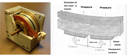
Speaking of exception while emphasizing principles may not make much sense, but the ultrasonic motor, invented by Mr. Toshio Sashida, does not require an air gap. The motor, as shown in Figure 6 (a photo and an illustration), rotates by a fictional force generated when piezoelectric ceramics contact the rotor’s surface.
The ultrasonic motor, which can be used where an electromagnetic motor cannot be used, is an important motor that plays complementary roles in motion control technology. I will touch upon the significance of the ultrasonic motor in my next column.
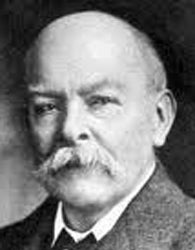
(1852-1914)
Having been born in Manchester, England, Poynting achieved an excellent academic record in physical mathematics at the University of Cambridge, and spent the latter half of the 1870s studying under James Maxwell at Cavendish Laboratory.
Poynting worked as a professor of Physics at the current University of Birmingham from 1880, presenting his first theory on energy flow in 1884.
Poynting then engaged in the research of pressure and tangential force by using optical irradiation, before passing away in the year when A Text-book of Physics, an epic that he co-wrote with J.J. Thompson, Nobel laureate in physics, was released. Strangely, not many, even in Manchester, know about this great physicist.
