SHAPER CUTTER / How to examine the helical guide common use
The helical movement of the cutter is generated by a helical guide.
The lead of the guide must be equal to the axial pitch of the helix of the cutter.
If it’s available a helical guide with a lead L you can choose, sometimes,
the characteristic of the cutter in accordance with the lead L.
This means that with a single guide you can use different shaper cutters.
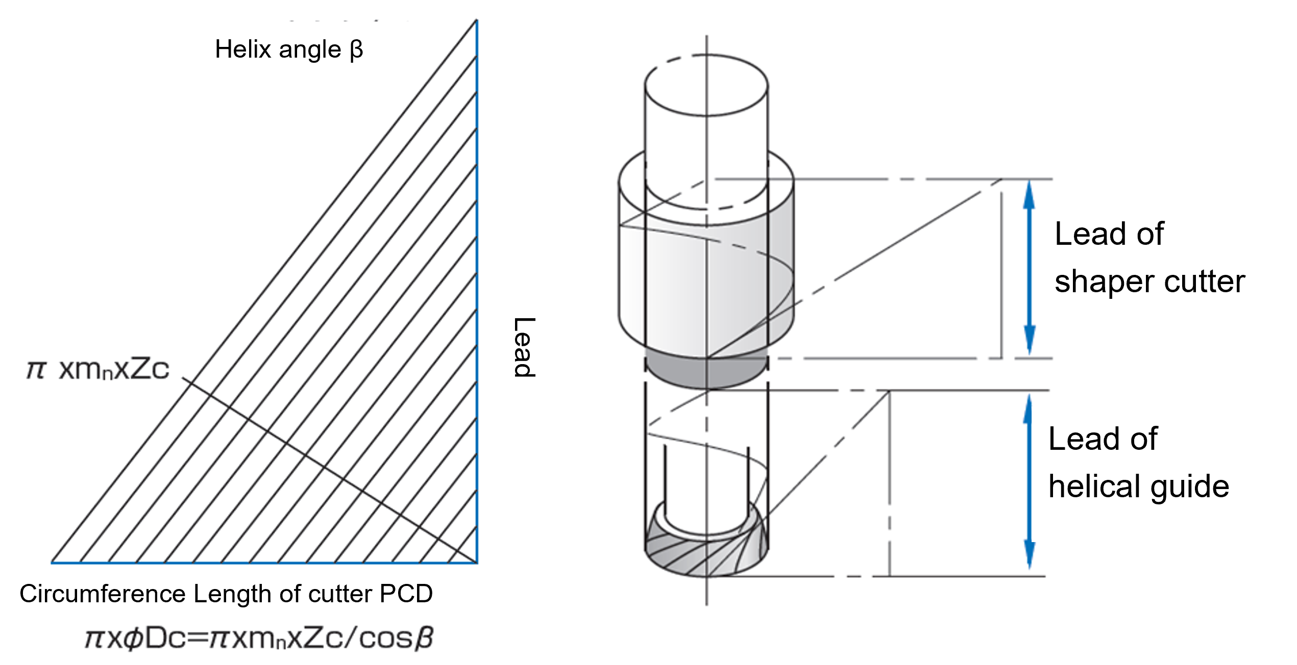
It can be calculated with the formula as follows,
No.1
- L=π×mn×Zc/ sin β
- mn: Normal Module
- β : Cutter helix angle(°)
- Zc : Numbers of cutter tooth
Condition
- 1.L should be as same as the helical guide lead you like to use.
- 2.Helix hand of the cutter should be opposite hand of the gears for external gears, on the other hand, for internal gears, should be the same hand as the gears.
1. Calculate Ideal Lead length for 2 shaper cutters
- Cutter A
- Module 2.0
- Helix angle 30°RH
- Cutter NT 71
- L = 892.2123mm
- Cutter B
- Module 2.5
- Helix angle 25°RH
- Cutter NT 48
- L = 892.0370mm
2. Calculate Lead angle error in case of the shared guide
- a)Calculate the helical angle of Cutter B in case of sharing the guide lead of Cutter A
- Cutter B/ Module 2.5, NT 48
- Shared Guide lead 892.2123mm
β’=Asin(Mn*Zn*PI/Shared guide lead) - β’= 24.99475 degrees
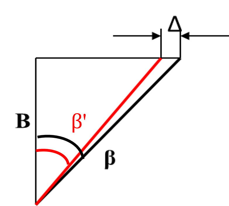
- b)Calculate the lead angle error fHβ △
fHβ Δ=B×(tan β’-tan β) - B (gear width at inspection process)=24mm
- fHβ = -0.00267 ≒ 3μm
- If the tolerance of fHβ is acceptable with 3μm error,
2 cutters can be cut with one guide lead 892.2123mm